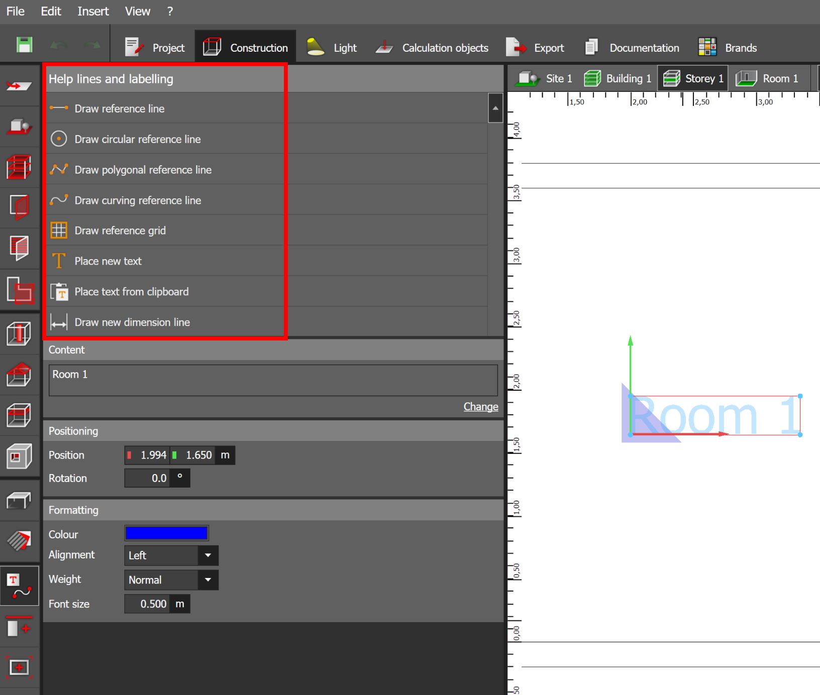
Actions in the help lines and labelling tool
Print
Modified on: Mon, 20 Feb, 2023 at 3:02 PM
In this tool you have the possibility to draw reference lines and dimension lines as well as to place and edit texts in order to simplify your planning activities.
Draw reference line
Reference lines are freely-placeable objects used to position objects (lights, furniture, calculation objects, points of the room, points of extrusion bodies or points of calculation surfaces) on them and align them . A reference line is defined simply by clicking the start point and clicking the end point again.
Before drawing the reference line, you can also set whether you need parallels of the reference line. If yes, you can define the distance and the number of parallels.
Draw circular reference line
With this function you can easily draw a circular reference line. Once the circle is drawn, you can change the radius and the circumference as well as the start and end angle.
Draw polygonal reference line
With this function you can easily draw a polygonal reference line. With each mouse click you set another point and finally you can close the polygon with a right click on the mouse.
If you subsequently want to add another point to the polygonal reference line, you can do this by selecting the polygonal reference line and right-clicking on the mouse to click on "Add point".
In addition, you can still decide whether the polygon should be closed or open. First, the polygon will be closed.
Draw curving reference line
With this function you can easily draw a curved reference line. With each mouse click you set another point and finally you can close the reference line with a right click on the mouse.
If you subsequently want to add another point to the curved reference line, you can do this by selecting the reference line and right-clicking on the mouse to click on "Add point".
In addition, you can still decide whether the polygon should be closed or open. First of all, the polygon will be closed.
Draw reference grid
With this function you can draw a grid of reference lines by setting the start point of the grid with the first mouse click and the end point of the X-axis with the second mouse click. Finally, you must determine the size of the Y-axis with the mouse and close the grid with a third mouse click.
Once the grid has been drawn, you can still change the position, length and width of the grid as well as the line spacing of the X and Y axes and the rotation.
Place new text
With this function you can add new text to your project. After you have determined the text and the position, you can still change the colour, alignment, weighting and font size.
Place text from clipboard
With this function you can insert a text into your project that has been saved in the clipboard. After you have determined the text and the position, you can still change the colour, alignment, weighting and font size.
Draw new dimension line
To enter the dimensions of your project in the drawing, you can draw dimension lines and adjust them as required. You position the start and end points using the manipulator and finally decide how the dimension line should be displayed. You can then change the type of dimensioning, the display and the text size of the dimensioning under "Formatting".
Did you find it helpful?
Yes
No
Send feedback Sorry we couldn't be helpful. Help us improve this article with your feedback.